Table of Content
Find the data sheet for the 4060 multivibrator integrated circuit . It will show how to wire the 4060 to operate as a time generator in conjunction with a 4013 flip flop IC. Support discrete components and the wiring of the support discrete components will be shown on the data sheets. Acquire an electronics prototyping breadboard. Programming and assembly were not too difficult.
The program is a bit messy but I did as best as I could to make it clean. Now you will need to choose the right resistor for current limiting to 3 LEDs in parallel. I made a common cathode display which means the all the negatives leads are connected together. But as I said In the parts list you will need 130 LEDs and the other 4 LEDs are going to be used as dots that separate the hours, minutes and the seconds. 4) about 10 resistors for the current protection.
TOP SALES! The best laser head for your 3D printer / CNC machine / engraving frame.
And you can choose what digit you want to power by connecting the negative leads of the display to ground and sending the data to the positive segment leads. Multiplexing works by switching between the digits one by one very fast and by so creating a illusion that all of the displays are working in the same time. The clock is made of six seven segment displays which make up the display. The below two blocks “Set Time” and “Set Date” are used to set the time and date in RTC which is found inbuilt in evive. We need to set the time and date using potentiometers and tactile switch of evive.
Thanks to all authors for creating a page that has been read 157,607 times. WikiHow is a “wiki,” similar to Wikipedia, which means that many of our articles are co-written by multiple authors. To create this article, 23 people, some anonymous, worked to edit and improve it over time. This article has been viewed 157,607 times. Wire pin 11 of the first 7490 to the clocking input of the second 7490.
Step 5: Advancing the Wall Clock
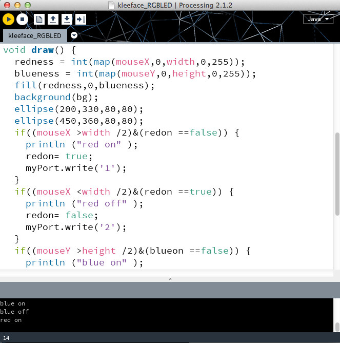
The LED will turn “red” at the position where the hour hand points to. I am able to do simple programs for the Arduino, but a clock is a bit above my pay grade, so I used their code. There are a few real-time clocks available for the Arduino, and after doing a little research, went for a DS3231, which seemed to be the best of the bunch.

While many digital clocks are available commercially, you can also build your own from components. Follow these tips to learn how to make a digital clock. Acquire the 4060, 4013, breadboard sockets for those parts, and all discrete support components identified in the data sheets. Build the 1 Hz time base on 1 corner of the breadboard.
Step 1: RGB LED in place of Clock Hands
Provide the ability to set the hours section of the counter. Wire the output from pin 8 of the fourth 7490 to the normally closed contact of a single pole double throw switch. Wire the normally open contact of the switch to the 1 Hz time base. Wire the wiper of the switch to the clock input of the fifth 7490. Provide the ability to set the minutes section of the counter.

Time is kept using a CR3203 battery, which is good for a year or more. The plastic mount for the LEDs I designed and made on the 3D printer. I needed a spacer inside the frame, so printed that as well.
Step 8: Coding the Clock
Combine the butter and sugar, beating until lightened and creamy. They are all basically the same dough from different origins. Some have variations with different nuts and flavorings added. STEP FOUR- The dough will be coarse and crumbly but will stick when you press it together. STEP TWO- Combine the butter and sugar, beating until lightened and creamy.
Cool completely then toss in powdered sugar again. Do a Google image search for "circuit diagram of a digital clock," you'll see many examples. Wire pin 11 of the third 7490 as the clocking input of the fourth 7490. This 7490 is the tens of minutes counter. Sequence the time clocking signals.Connect the 1 Hz time base of the clocking input to the clocking input of the first 7490.
It should still be cool to the touch but indent easily when you press it with your finger. When toasting the nuts, cool them completely before adding to the batter so they don’t melt the butter. Make sure your butter is just room temperature, the butter should sit at room temperature for about 1 hour. STEP FIVE- Press roughly a tablespoon of dough in your hand squeezing and rolling into a 1-inch ball shape.
Pendulums are unusable on moving platforms, such as a ship, and springs unwind more and more slowly as they release stored up tension. The use of sweep hands allowed these mechanical time bases to be presented in a mechanically driven display. With the perfecting of multivibrator chips, electrical circuits could be built that could accurately keep time under a wide range of conditions. As the time base had switched from mechanical to electrical, the time display had to follow suit. Display devices called 7 segment displays were designed to allow the time to be shown numerically.


No comments:
Post a Comment